We present an algorithm and a system for accelerated display of large environments. We represent a given geometric dataset using a scene graph and automatically compute levels of detail (LODs) for each node in the graph. We further augment the LODs with hierarchical levels of detail (HLODs) that serve as higher fidelity drastic simplifications of entire branches of the scene graph, where drastic refers to a reduction in polygon count by an order of magnitude or more. Our rendering system leverages the unique properties of our HLOD scene graph to allow a user to explicitly choose between a specified image quality or target frame rate. We efficiently render LODs and HLODs using display lists. The resulting system, SHAPE, has been used to render complex CAD environments composed of tens of millions of polygons. SHAPE achieves significant speedups in rendering these large static environments.
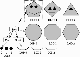
Traditional LOD methods can typically only simplify a single object at a time. Given a scene containing multiple objects, these methods can only minimize errors local to individual objects and not the scene as a whole. Hierarchical LODs, or HLODs, are a generalization of traditional LOD methods to hierarchical aggregations of objects. We generate HLODs by simplifying separate portions of a scene together, producing higher fidelity global approximations, especially for drastic simplifications.
|
We represent the environment using a scene graph and compute LODs for each node. We then compute HLODs at each node in a bottom-up fashion based on these LODs. An HLOD of a node in the scene graph is an approximation of the node as well as its descendants. Therefore, if we render a node's HLOD while traversing the scene graph, we do not need to visit its descendants. In this way we can aggressively cull out entire portions of the scene by merely rendering the HLODs at a node when appropriate (see Figure 1).
Some of the key features of our system include:
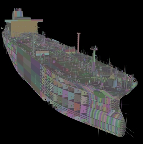
Our algorithm has been implemented as part of our system, SHAPE, and used to render large environments such as a power plant consisting of 13-million triangles and the Double Eagle tanker consisting of 82-million triangles.
HLODs are generated by hierarchically grouping nodes in a scene graph and simplifying them together. The algorithm also partitions spatially large objects in order to gain limited view-dependent rendering capabilities for these objects.
The HLOD generation algorithm uses a combination of an LOD computation algorithm and hierarchical clustering. The underlying LOD algorithm needs to handle topological simplification and be able to combine a collection of non-overlapping or disjoint objects. In SHAPE, we use GAPS. After LODs are computed for each individual node in the scene graph, our algorithm computes HLODs in a hierarchical bottom-up manner. The HLODs of a scene graph are computed as follows:
More details can be found in the UNC Technical Report, "Simplification Culling of Static and Dynamic Scene Graphs" (TR98-009) and Carl Erikson's PhD Dissertation.
|
We assume that for each environment, a hierarchical scene graph representation is given. If not then SHAPE is capable of creating a hierarchy using partitioning. We use grouping to create a more spatially coherent scene graph: if a node has more than two child nodes, we use an octree spatial partitioning to find nearest neighbors and use these pairings to create a hierarchy with better spatial coherence. This not only aids view-frustum culling, but also leads to higher quality HLODs.
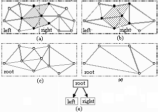
Since we use static LODs, spatially large objects can pose a problem. When the viewer is close to any region of a spatially large object the entire object must be rendered in high detail, even though portions of it may be very far from the viewer. To alleviate this problem, we partition the model spatially to gain limited view-dependent rendering capabilities. We simplify each partition while guaranteeing that we do not produce cracks between partitions by imposing restrictions on simplification (See Figure 2). Finally, we group the unrestricted polygons of these partitions hierarchically and generate HLOD approximations of them.
One can view the HLODs generated through the partitioning process as representing a discrete approximation of view-dependent simplification (See Figure 8). An added benefit of partitioning is that it allows us to perform view-frustum culling on parts of the object that lie outside the view frustum.
Next, we discuss our algorithm for rendering a scene graph containing LODs and HLODs. We begin with a description of how HLODs can be used to cull out entire portions of the scene graph, and follow with an explanation of our image-quality and frame-rate targeting modes.
We assume the polygonal simplification algorithm we use to generate LODs and HLODs is capable of producing a distance error bound for these approximations. This error measures the quality of an approximation based on deviation from the original object, and is projected onto the view plane to determine the screen-space error of the LOD or HLOD.
Rendering the scene graph involves determining which LOD or HLOD to render for each node. Our algorithm first determines if it can render an HLOD at the node by comparing the HLOD's projected screen-space error to the current error tolerance. If no HLOD meets the current error tolerance, we select an LOD to represent the node and then recursively traverse each of its children. By rendering an HLOD at a node we are able to cull the entire subtree below the node by substituting a simpler representation.
More details can be found in the UNC Technical Report, "Simplification Culling of Static and Dynamic Scene Graphs" (TR98-009) and Carl Erikson's PhD Dissertation.
In this mode, the user is allowed to specify a desired image quality in terms of maximum screen space deviation. While rendering, the projected screen-space error associated with each LOD and HLOD is used to determine an acceptable representation given the image quality constraint.
The traversal of the scene graph starts at the root node. If the error bound associated with an HLOD of the root node satisfies the image quality requirement, we render it and stop the traversal. Otherwise, we render an appropriate LOD of the node based on the error bound and recursively traverse its children.
Our target frame-rate mode has the goal of rendering the best image possible within a user-specified frame-rate constraint. In our algorithm, we keep track of a target number of faces. This number is the best guess of how many polygons the system can render given the user-specified frame-rate constraint. This number is updated reactively: if we could not render the number of faces within the frame-rate constraint, the target number of faces is decreased for the next frame. Thus before each frame is rendered, we have a strict limit on the number of faces that can be drawn.
The algorithm starts with the coarsest HLOD of the root node of the entire scene graph. It attempts to refine the node with the most screen-space error by replacing it with its child nodes. If replacing a node would cause our algorithm to render more polygons than the target number of faces, then this action is not allowed. We refine nodes until no more nodes can be replaced. More details can be found in Carl Erikson's PhD Dissertation.
The main benefit of using HLODs is that they provide high quality and drastic approximations for groups of objects. Using only LODs, groups of objects tend to break apart or disintegrate at coarse approximations. However, by using a combination of LODs and HLODs, we can produce more solid-looking, drastic approximations without having to resort to dynamic techniques. Because HLODs promote the merging of objects in close proximity, they are most effective on scenes where objects are closely spaced together. Most CAD environments fall in this category.
We show the visual difference between LODs and HLODs for drastic approximations of the power plant (Figure 3), Double Eagle (Figures 4-5), and Ford Bronco (Figures 6-7) environments. Note how the solid shape of these scenes tends to disappear when using only LODs. By pooling the geometry of several objects into HLODs, we are able to better preserve the general shape and surface area of these environments further into the simplification process.
For the benefit of those with low bandwidth connections, the figures are located in the images page.
Our work was supported by: an Alfred P. Sloan Foundation Fellowship, ARO, Honda, Intel Corp., NIH, National Center for Research Resources, NSF, ONR, NSF/ARPA Center for Computer Graphics and Scientific Visualization, NCAA Graduate, NSF Graduate, and Intel Fellowships.
Wesley Hunt.
Last updated: April 28, 2000