Examples of each feature are below
|
|
|
|
|
|
|
|
|
|
|
|
|
|
|
|
|
|
|
|
|
|
|
|
|
|
|
Understanding Perspective
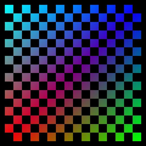
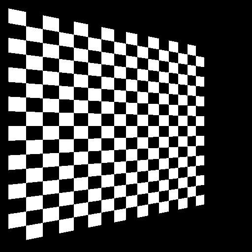
The visible differences between perspectively correct
and incorrect interpolation is most noticable when looking at the texture
mapped quads below. Look closely at the 45 degree quads, notice in
the perspectively incorrect quad, the color is uniformly distributed just
like the flat quad. The correct image shows the colors closer to
the viewer dominate more of teh image, just like the elongated squares
on the checkerboard. It is amazing how almost all hardware interpolated
colors incorrectly, checkout my hardware
evaluation on color interpolation.
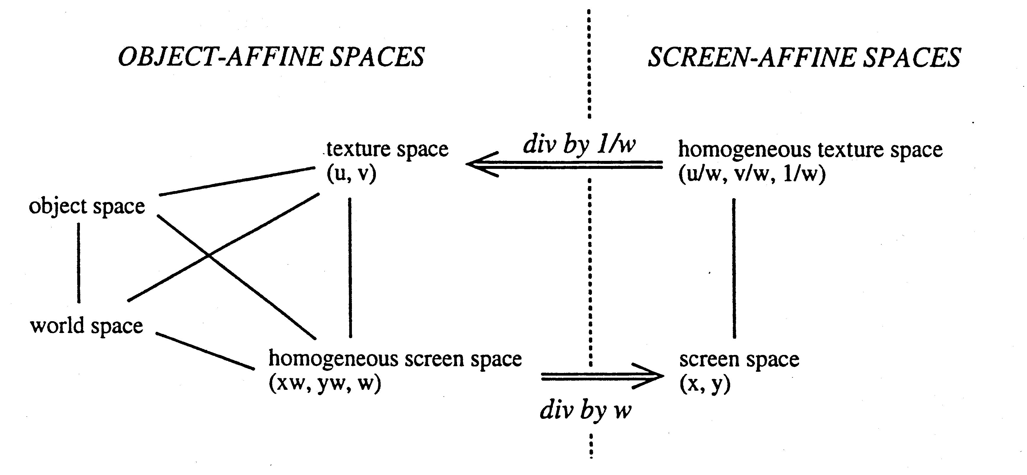
To correctly interpolate colors and texture coordinates,
they must first be divided through by homogeneous coordinate w.
The w coordinate becomes 1/w. These new values are
then linearly interpolated in screen space. At each pixel, the coordinate
is then divided by the interpolated 1/w (essentially multiplying
by w) to obtain the correct value. The transformation between
spaces is best shown by Paul Heckbert and Henry Moreton "Interpolation
for Polygon Texture Mapping and Shading"

The first batch of images below show how perspective effects an image.
(click on images for larger, more clear versions)
Clamping Textures
Texture coordinates may be assigned values outside
the range [0,1). Ther are two methods for dealing with this, texture
clamping and texture repeating. When clamping is specified, any coordinate
outside the range is clamped to the min, max appropriately. The actual
texel range is:
s = [1/(2*TW), 1-1/(2*TW)]
t = [1/(2*TH), 1-1/(2*TH)]
Where TW is the texture width and TH is the texture height. (Note: OpenGL currently only supports 2nx2n textures). This is because the actual texels are in the middle of the square, similar to the way we perform rasterization at the pixel level. The images below demonstrate texture clamping.
(click on images for larger, more clear versions)
Repeating Textures
If repeat mode is used, any coordinate outside the
range of texels is wrapped around to the opposite side of the texture.
When a coordinate is greater then 1, the floating point fraction is used.
When a coordinate is less then zero, the coordinate - floor(coordinate)
is used. For example, the texture coordinate (-0.1, 0.5) will
wrap to (0.9, 0.5) not +0.1. The general formula for
wrapping textures is:
coordinate = coordinate - floor(coordinate)
Note that this is only necessary for values less then zero, if the value is positive a simple mod can be used. Below are images demonstrating texture wrapping.
(click on images for larger, more clear versions)
Replace and Modulate
When in replace mode, the color at each pixel is
determined by the color obtained from the texture map (nearest or linear
filtering). Any colors specified on the geometry itself is ignored.
When modulation is specified, the color of each pixel is determined by
the color obtained from the geometry multiplied by the value obtained from
the texture map (nearest or linear filtering). Below are images of
replace (decaling) and modulation.
(click on images for larger, more clear versions)
|
|
|
 |
 |
 |
 |
Nearest and Bilinear Filtering
When looking at images of the checkerboard texture,
you will notice aliasing (jaggies) on the lines. This is where the
line jumps a pixel. This type of image uses nearest filtering.
The color of the pixel is determined by the nearest texel in the texture
map.
A way to smooth out the lines (antialias) is to
use linear filtering. The term linear is a generalization, since
we can perform 1D (linear) 2D (bilinear) and 3D (trilinear) filtering using
the same technique. In the images here, I have used bilinear interpolation,
since I have 2D texture maps. The weighted average of the four closest
texels is used to color each pixel. The four closest texels are determined
depending upon which wrapping mode is used (clamp or repeat).
When clamping is used, if any of the four texels falls out of the texel
range, the texel on the boarder is used in the average twice (or more depending
on the situation). If repeating textures, the texel that is on the
opposite side (wrapped around) of the texture is used in the average.
Using this method it is easy to understand how this can be applied to 1D
(2 texels) and 3D (6 texels).
There are pro's and con's for using each method.
If speed is desired, then the nearest filter will run the fastest, while
the image may appear quite jagged depending on the texture and orientation.
If quality is preferred, then perhaps linear filtering is appropriate,
at the cost of performance. One common consequence of linear filtering
is a blurring of the lines, which can easily be seen in the various images
displayed.
Putting it all Together
Now that you have seen the various methods of texture
mapping, I have put together a high resolution (1600x1200) image displaying
each feature. Note that the entire image is rendered perspectively
correct, I didn't have to do this, but it just looks much better!
Click on the image for the full size.
The Interactive Demo
To get a feel for how things work, try out the demo
program using the SoftGL system. Notice how the textures are distorted
when using perspectively incorrect interpolation. Here are the controls:
| Mouse | Used to Rotate |
| Left Button | Locks mouse movements to controls |
| , | Zoom In |
| . | Zoom Out |
| 1 | Use Texture Map 1 (Repeat, Nearest) |
| 2 | Use Texture Map 2 (Clamp, Bilinear) |
| 3 | Replace Mode |
| 4 | Modulate |
| b | Toggle Backface Culling |
| s | Toggle Smooth/Flat Color Interpolation |
| l | Toggle Lighting |
| t | Toggle Texture Mapping |
| p | Toggle Test Plane |
| c | Toggle Perspective Correction |
| \ | Toggle Moving/Stationary Lights |
| ` | Toggle Deforming/Stationary Cube |
| ; | Decrease Spotlight Exponent |
| ' | Increase Spotlight Exponent |
| [ | Decrease Spotlight Cutoff |
| ] | Increase Spotlight Cutoff |
| ESC | Exit |
| SPACE | Toggle SoftGL vs OpenGL mode
*most* OpenGL supports only perspectively correct texture mapping. |
(click on images for larger, more clear versions)
|
|
|

notice the difference in the faces. |

click to see a larger version |
| home |